Introduction
Modern vehicles depend on engines to create motion and useful power for travel and work. The phrase Components of an Engine refers to the major mechanical parts that cooperate to convert fuel energy into rotation that moves wheels or propellers. A clear view of these parts helps students, technicians, and curious drivers understand what occurs inside the metal housing under the hood. Each piece has a clear task and works with other parts in a steady cycle of intake, compression, power, and exhaust. When these parts stay aligned and well lubricated the engine runs with strength, calm sound, and steady output across many hours of service.
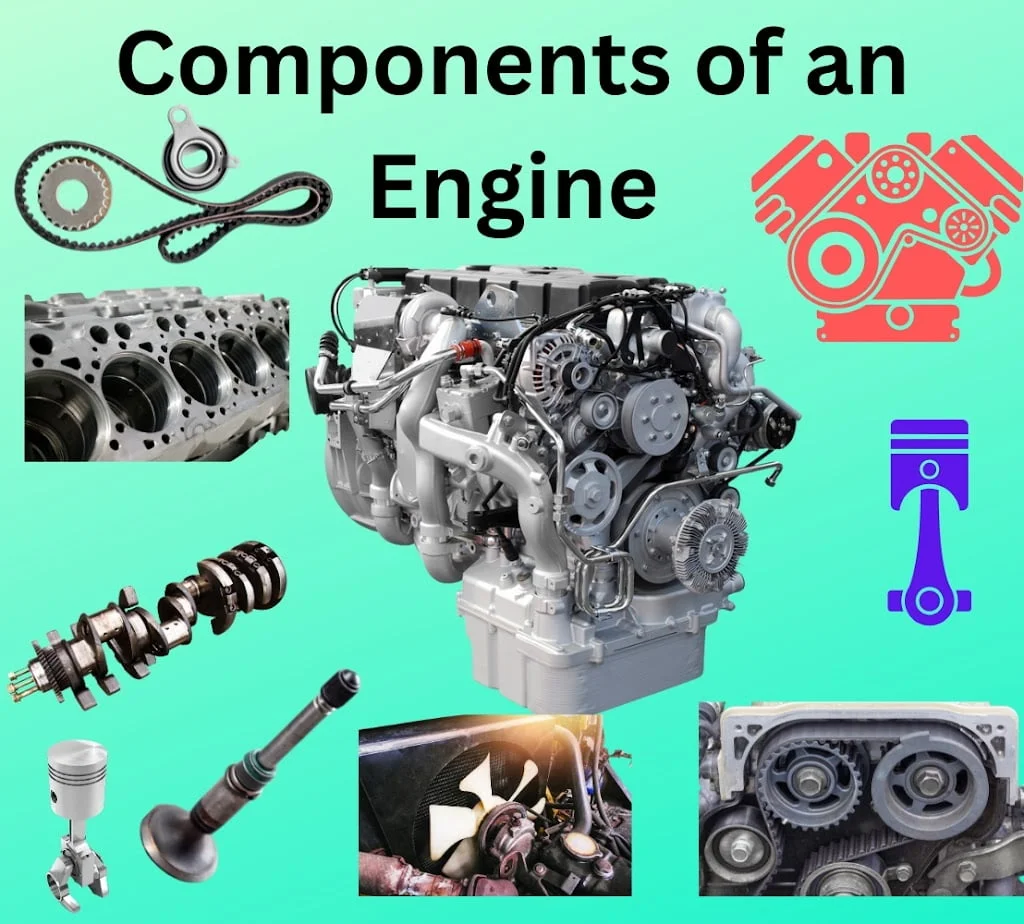
Components of an Engine
The major Components of an Engine form a strong mechanical system that transforms heat energy from fuel into motion. Each part connects with another in a precise layout that allows energy to move through the system with very little loss. Designers select materials, shapes, and sizes so that these parts survive high pressure and heat during daily operation. A typical internal combustion engine uses cylinders, pistons, rods, and shafts that work in a repeating cycle. When these elements cooperate smoothly the engine delivers steady torque, stable speed, and dependable service across long driving periods.
Main Parts in an Engine System
Several mechanical units create the internal structure of an engine. Each unit performs a defined task while supporting nearby parts during the combustion cycle. The main elements usually include a cylinder block, crank case, cylinder head, piston assembly, connecting rod, crankshaft, and camshaft. These pieces operate in coordination while the engine runs through repeated strokes. Engineers design the structure so that each motion flows into the next without delay. A smooth sequence of motion improves fuel use, limits wear, and keeps vibration at a safe level during vehicle operation.
- cylinder block
- crank case
- Cylinder Head
- Piston
- Connecting Rod
- Crankshaft
- Camshaft
1.Cylinder Block
The cylinder block forms the main structural body of an engine. It holds the cylinders where combustion takes place and supports many moving parts during operation. Manufacturers usually build this block from cast iron or aluminum alloy so that it resists pressure and heat during combustion. Inside the block engineers machine smooth cylindrical bores where pistons travel up and down in a repeating motion. These bores remain aligned with the crankshaft and connecting rods. Accurate alignment keeps friction low and ensures that the mechanical movement remains balanced during the engine cycle.


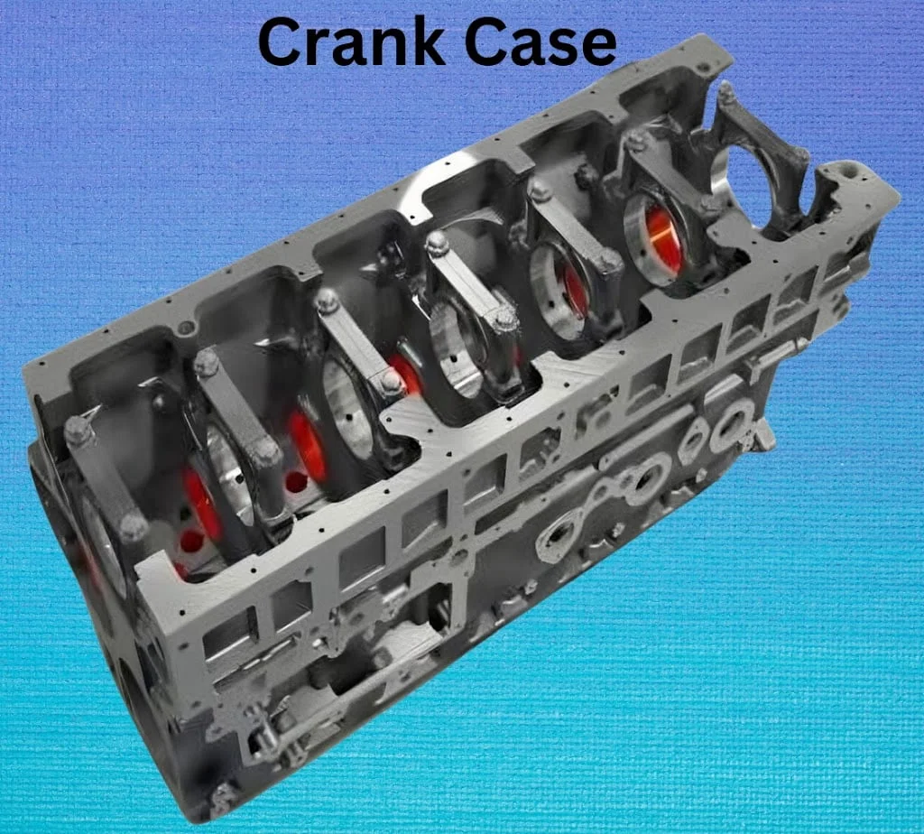
2.Crank Case
The crank case forms the lower chamber of the engine and supports the crankshaft assembly during rotation. This chamber acts as a protective housing that keeps the crankshaft aligned while it converts piston motion into rotary movement. Strong walls within the case hold bearing supports that keep the crankshaft stable as it spins at high speed. The structure also shields internal parts from dirt and helps maintain a steady supply of lubricating oil. A well built crank case reduces vibration, improves stability, and protects moving parts during long hours of engine operation.
- It forms the lower part of the engine. It accommodates crankshaft. The crankshaft is a long straight piece of metal in a vehicle that connects the engine to the wheels and helps turn the engine’s power into movement.
- The crankshaft rests on supports at both ends inside the crankcase walls. The crankcase provides these support points. In engines with longer crankshafts, engineers also place an additional support in the middle, and the crankcase includes a provision for that central support as well.
3.Cylinder Head
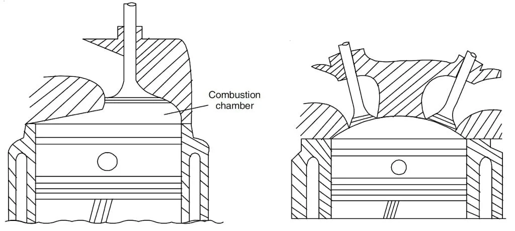
The cylinder head forms the upper section of the engine assembly and closes the top of the cylinder block. This part contains passages, valves, and chambers that guide air and fuel during combustion. Designers shape the combustion chamber to improve fuel burning and power output. Precision machining ensures that the head fits tightly against the cylinder block so pressure does not escape during operation. When the cylinder head performs its role correctly the engine maintains strong compression, stable combustion, and efficient power generation through every working cycle.
- Cylinders are where the magic happens.They provide the space for the piston to move up and down during the combustion cycle.Engines can have different numbers of cylinders, such as four-cylinder, six-cylinder, or eight-cylinder configurations.
- Engineers design the cylinder head to hold the inlet and exhaust valves. It also forms the top part of the combustion chamber. Designers shape the combustion chamber in various ways to achieve effective fuel combustion.
- Manufacturers use cast iron or aluminum alloy to make the cylinder head. They machine the surface to ensure smooth installation of various components.
- Engineers install a cover on the cylinder heads to prevent noise and vibration from reaching the automobile body. They make the cover using a three-layer sheet: the outer two layers consist of metal, while the middle layer contains plastic. This plastic layer blocks the transmission of noise and vibration from the engine.
4.Piston
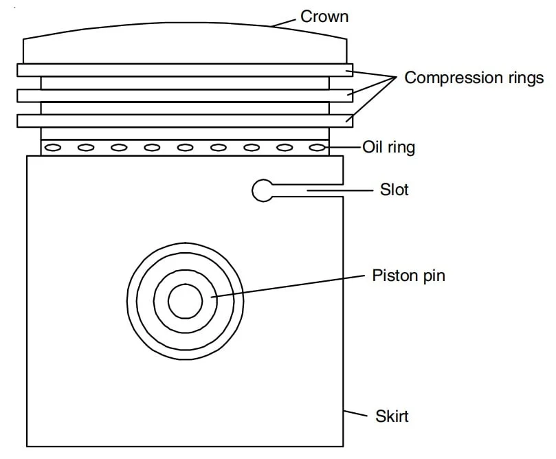
The piston moves inside each cylinder and receives the force produced during combustion. Hot expanding gases push the piston downward which transfers force through the connecting rod toward the crankshaft. This motion repeats rapidly while the engine runs. The piston must remain sealed against the cylinder walls so that pressure does not escape. Rings placed around the piston create this seal and keep oil from entering the combustion chamber. A properly fitted piston maintains compression, reduces friction, and allows the engine to produce steady mechanical power.
- Pistons play a crucial role by moving within the cylinders. They connect to the crankshaft through connecting rods and perform a reciprocating motion. The combustion force pushes the piston downward and converts thermal energy into mechanical energy.
- The piston moves inside the cylinder and has reciprocatory motion. It is air tight and does not allow the leakage of charge and hot gases with the help of rings which form a part of piston ring assembly.
- The top portion of the piston, called the crown, forms the upper surface of the piston. The piston assembly includes piston rings and a piston pin as integral parts. The skirt forms the lower-most part of the piston.
5.Connecting Rod
The connecting rod links the piston to the crankshaft and transfers motion between these parts. During engine operation the piston moves in a straight path while the crankshaft rotates in a circular path. The connecting rod allows this motion change to occur smoothly. Its small end holds the piston pin and its larger end grips the crank pin on the crankshaft. Engineers shape the rod with strong cross sections so that it handles repeated force without bending or breaking during continuous engine cycles.
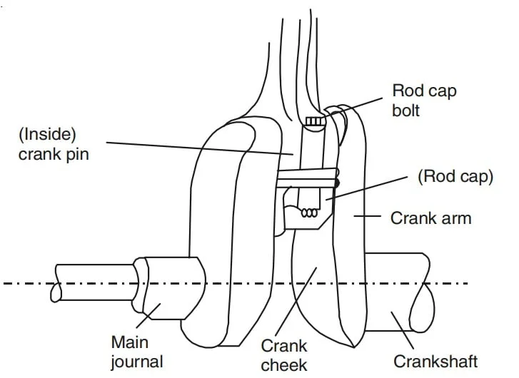
6.Crankshaft
The crankshaft converts the straight line movement of pistons into rotary motion that drives the vehicle. As pistons travel up and down the connecting rods push against offset crank pins on the shaft. This design turns linear force into rotation. Bearings support the shaft along its length so that it spins smoothly under load. Balanced counterweights reduce vibration while the engine operates at high speed. When this shaft rotates it sends mechanical power through the drivetrain toward the wheels of the vehicle.
- The part of the crank shaft inside the connecting rod bearings is called the crank pin and those inside the main bearings are called the main journals (Fig. 6).
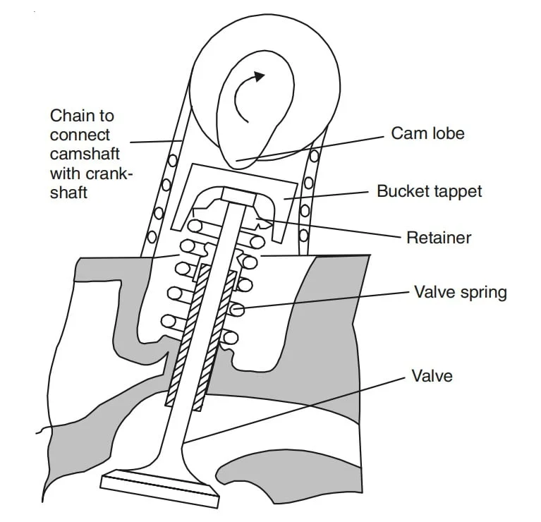
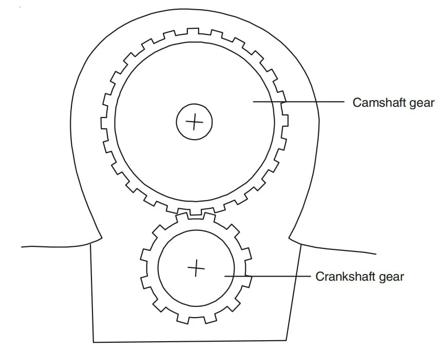
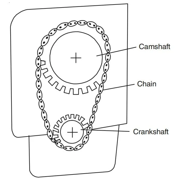
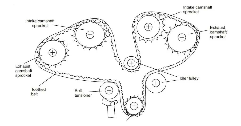
7.Camshaft
The camshaft controls the opening and closing of engine valves during the combustion cycle. Each cam lobe presses against valve components at the right moment so that air and fuel enter the cylinder and exhaust gases leave it. Accurate timing between the camshaft and crankshaft ensures that this process stays synchronized with piston motion. When the camshaft rotates correctly the engine breathes efficiently and maintains stable combustion during operation.
- It is responsible for opening/closing of valve.
- The camshaft rotates at `left(frac{1}{2}right)` the speed of crankshaft as the valves open only once in complete cycle that require two crankshaft rotations in 4-stroke engine.
Conclusion
Knowledge of the Components of an Engine gives readers a clear view of how mechanical power develops inside modern vehicles. Each element plays a specific role in the combustion process and supports the motion created by other parts. The cylinder block forms the structure, pistons move within cylinders, rods transfer force, and the crankshaft turns this force into rotation. The camshaft guides valve timing so fuel and air move correctly through the system. When these components remain aligned, cooled, and lubricated the engine delivers strong performance and dependable service during everyday travel.