Introduction
Resistance
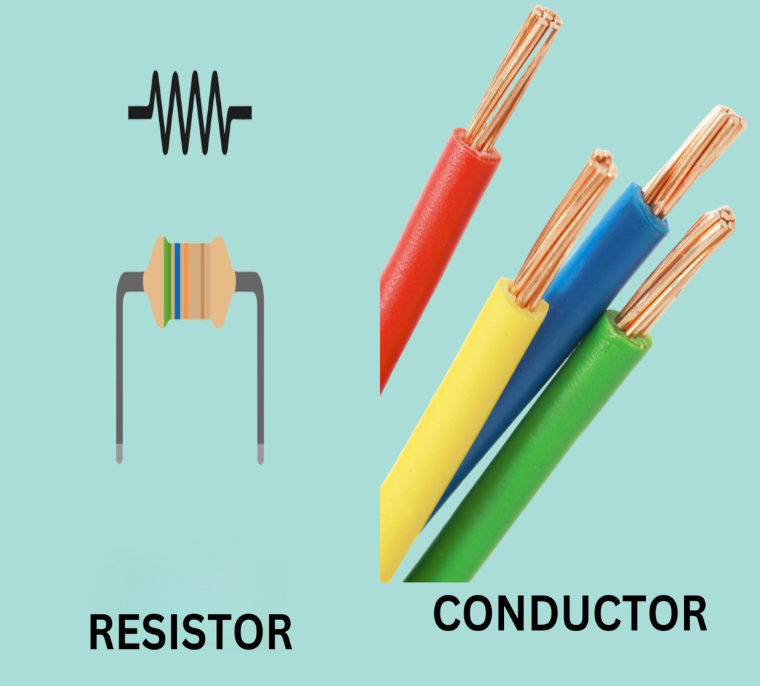
We define resistance as the opposition a substance offers to the flow of electric current.
A resistor is a passive, two-terminal electronic component specifically designed to limit or control the flow of electric current within a circuit. In essence, it resists the movement of electrons, thereby converting electrical energy into heat. As a result, resistors play a vital role in managing energy within electronic systems. Moreover, they are crucial for several reasons, including voltage division, current limiting, and providing stability to electronic circuits. In addition, resistors help protect sensitive components from excessive current and contribute to the overall performance and reliability of electronic devices.
Free electrons create current as they flow through a substance. The atoms and molecules in the material obstruct this flow and create resistance. Metals like silver, copper, and aluminium allow electrons to pass easily and act as conductors. On the other hand, materials such as glass, rubber, mica, and dry wood block electron flow and function as insulators.
Note that resistance creates electrical friction, which generates heat as electric current flows. The moving electrons collide with the atoms or molecules in the substance, and each collision releases a small amount of heat.
Unit of resistance;The practical unit of resistance is the ohm, represented by the symbol Ω.
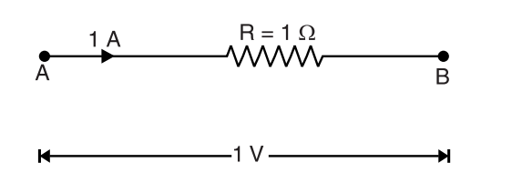
A wire has a resistance of 1 ohm if it releases 1 joule of energy (or develops 0.24 calorie of heat) when a current of 1 ampere flows through it for 1 second.
A little reflection shows that second definition leads to the first definition. Thus 1 A current flowing for 1 second means that total charge flowing is Q = I × t = 1 × 1 = 1 coulomb. Now the charge flowing between A and B (See above Figure) is 1 coulomb and energy released is 1 joule (or 0.24 calorie). Obviously, by definition, p.d. between A and B should be 1 volt.
Factors Upon Which Resistance Depends
- is directly proportional to its length i.e.
Specific Resistance or Resistivity
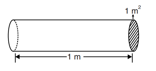
Hence specific resistance of a material is the resistance offered by 1 m length of wire of material having an area of cross-section of 1 `m^2`.
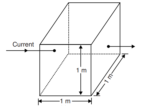
Specific resistance can also be defined in another way.Take a cube of the material having each side 1 m.Considering any two opposite faces, the area of cross-section is 1 `m^2` and length is 1 m
Hence specific resistance of a material may be defined as the resistance between the opposite faces of a metre cube of the material.
Unit of resistivity. We know R = `frac{rho l}a` or ρ = `frac{Ra}l`
- If the length is measured in metres and area of cross-section in `m^2`,then unit of resistivity will be ohm-metre (Ω m).
- If length is measured in cm and area of cross-section in `cm^2`,then unit of resistivity will be ohm-cm (Ω cm).
| S.No. | Material | Nature | Resistivity (Ω m) at room temperature |
|---|---|---|---|
| 1 | Copper | Metal | 1.7 × 10⁻⁸ |
| 2 | Iron | Metal | 9.6 × 10⁻⁸ |
| 3 | Manganin | Alloy | 48 × 10-8 |
| 4 | Nichrome | Alloy | 100 × 10-8 |
| 5 | Pure silicon | Semiconductor | 2.5 × 10³ |
| 6 | Pure germanium | Semiconductor | 0.6 |
| 7 | Glass | Insulator | 1010 to 1014 |
| 8 | Mica | Insulator | 1011 to 1015 |
The reader may note that resistivity of metals and alloys is very small.Therefore, these materials are good conductors of electric current. On the other hand, resistivity of insulators is extremely large. As a result, these materials hardly conduct any current. There is also an intermediate class of semiconductors. The resistivity of these substances lies between conductors and insulators.
Conductor
In electricity, a conductor refers to a substance that allows electric charge to flow smoothly. These substances conduct electricity well because they offer very little resistance to the movement of electrons. Engineers and electricians frequently use copper and aluminum as conductors due to their excellent conductivity and beneficial properties.
Conductance
Whereas resistance of a conductor is the opposition to current flow, the conductance of a conductor is the inducement to current flow.
Conductance is crucial for evaluating electrical circuits, as it indicates the ease of electricity passing through a conductor. High conductance materials facilitate current flow, while low conductance materials obstruct the flow of electricity.
The SI unit of conductance is mho (i.e., ohm spelt backward). These days, it is a usual practice to use siemen as the unit of conductance. It is denoted by the symbol S.
Conductivity
Applications of conductor
- Conductors are present in all aspects of our daily lives, seamlessly integrated into our technology-based society. They play a crucial role in transporting electric energy, from power lines to electronic circuits, enabling the functionality of our homes and devices.
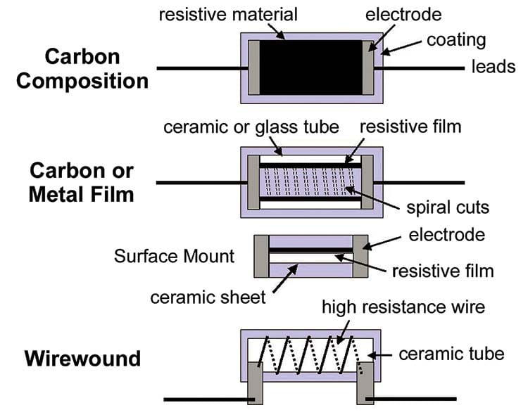
Types of Resistors
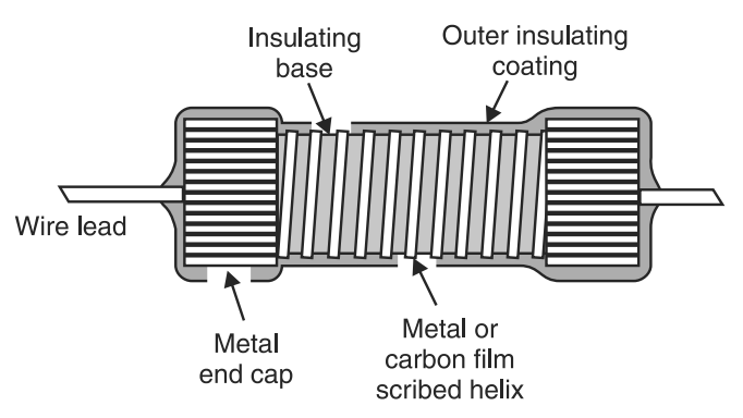
2.Film resistors
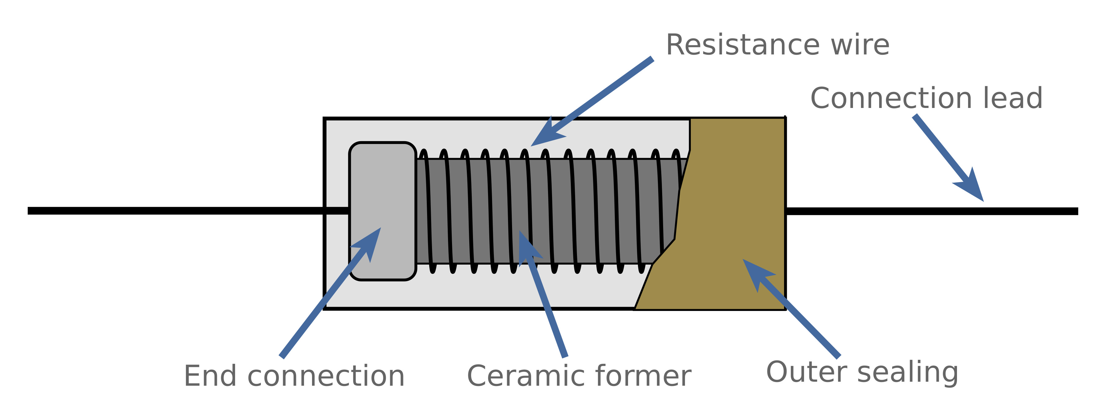
3.Wire-wound resistors
4.Cermet resistors
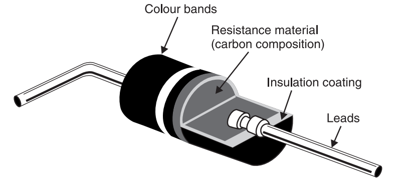
1.Carbon composition type
Carbon resistors are relatively inexpensive to build. However, they are highly sensitive to temperature variations. The carbon resistors are available in power ratings ranging from 1/8 to 2 W.
2.Film resistors
3.Wire-wound resistors
4.Cermet resistors.
Functions of Resistors
- Voltage Division: To bias the transistor and to put some reference voltages in it, engineers use resistors as voltage dividers. By placing resistors in a particular circuit, you could deliberately produce voltage ranges.
- Current Limiting: In most applications, controlling the amount of current flowing through a point is essential. Resistors serve as current limiters, regulating the flow to prevent damage to sensitive components like LED chips.
- Signal Conditioning: Engineers widely use resistors in signal processing and conditioning circuits to reduce or amplify signals, match impedances, and preserve signal integrity.
Applications and Importance of Resistors
In every digital device, simple as flashlights to the most complex computer systems one can see resistors.
- Audio Equipment: Audio equipment uses resistors in components such as volume controls, tone modification circuits, and signal filters.
- Power Supplies: Voltage law and modern days prescribing both use resistors in energy supply circuits.
- Transistors and Amplifiers: Transistors and amplifiers use resistors to establish bias and control gain within amplifier circuits.
- LED Current Limiting: For LED circles, the resistors offer ensure for varying reasons a number of which are that LEDs copy will likely burn out.
Conclusion
In essence, resistance and conductance are key principles that form the basis of electrical circuit behavior. Understanding these principles enables engineers to create new solutions, solve intricate issues, and push the boundaries of electrical engineering. Whether you're working on circuit design or exploring electrical phenomena, remember that resistance and conductance are essential in the field of electrical engineering.
