Introduction
In today's technologically advanced world, magnetization plays a fascinating role closely tied to the core principles of electromagnetism. It forms the foundation of many modern applications. Scientists and engineers must understand how magnetic materials behave under different conditions. In this blog, we explore the intriguing concept of Magnetic Hysteresis and dive into Magnetization Curves, commonly illustrated by the B-H Curve.
Understanding Magnetization
Magnetization occurs when a material becomes magnetic in response to an external magnetic field. This phenomenon happens because the material’s atomic or molecular magnetic moments align with the field. In simpler terms, a material gets magnetized when its magnetic domains align under the influence of a magnetic field.
The Magnetization (B-H) Curve Demystified
Key Components of the Magnetization (B-H) Curve
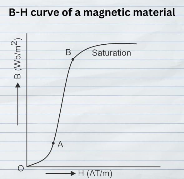
Magnetization Process
Saturation Point
Hysteresis Loop
Applications and Significance of Magnetization (B-H) Curve
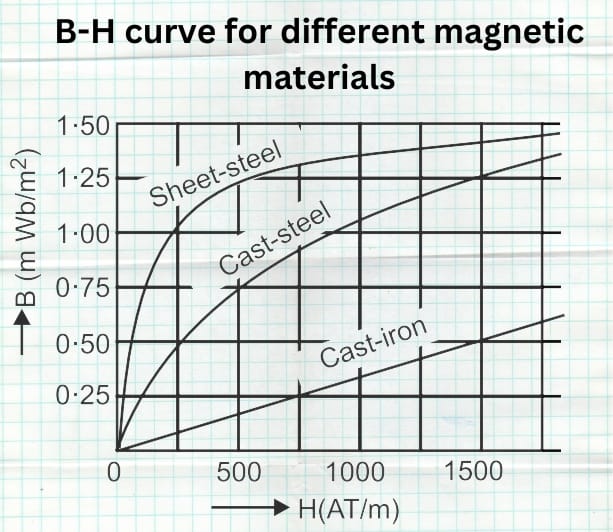
Material Selection in Electromagnetic Devices
Magnetic Storage Devices
Magnetic Sensors and Actuators
Magnetic Hysteresis
- When a magnetic material undergoes one complete cycle of magnetization—first in one direction and then in the other—the magnetic flux density BB lags behind the applied magnetizing force HH. This lagging behavior is known as magnetic hysteresis.
- Therefore, we refer to the lag of magnetic flux density BB behind the magnetizing force HH in a magnetic material as magnetic hysteresis.
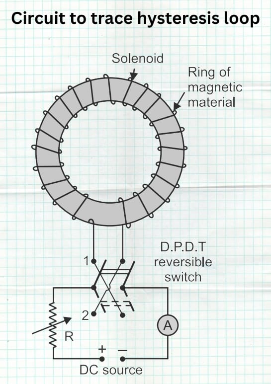
- The term hysteresis comes from the Greek word hysterein, which means “to lag behind.” To understand the full phenomenon of magnetic hysteresis, consider a ring made of magnetic material with a uniformly wound solenoid, as shown in Fig. 5. A DC source connects to the solenoid through a double-pole double-throw reversible switch, set initially to position ‘1’.
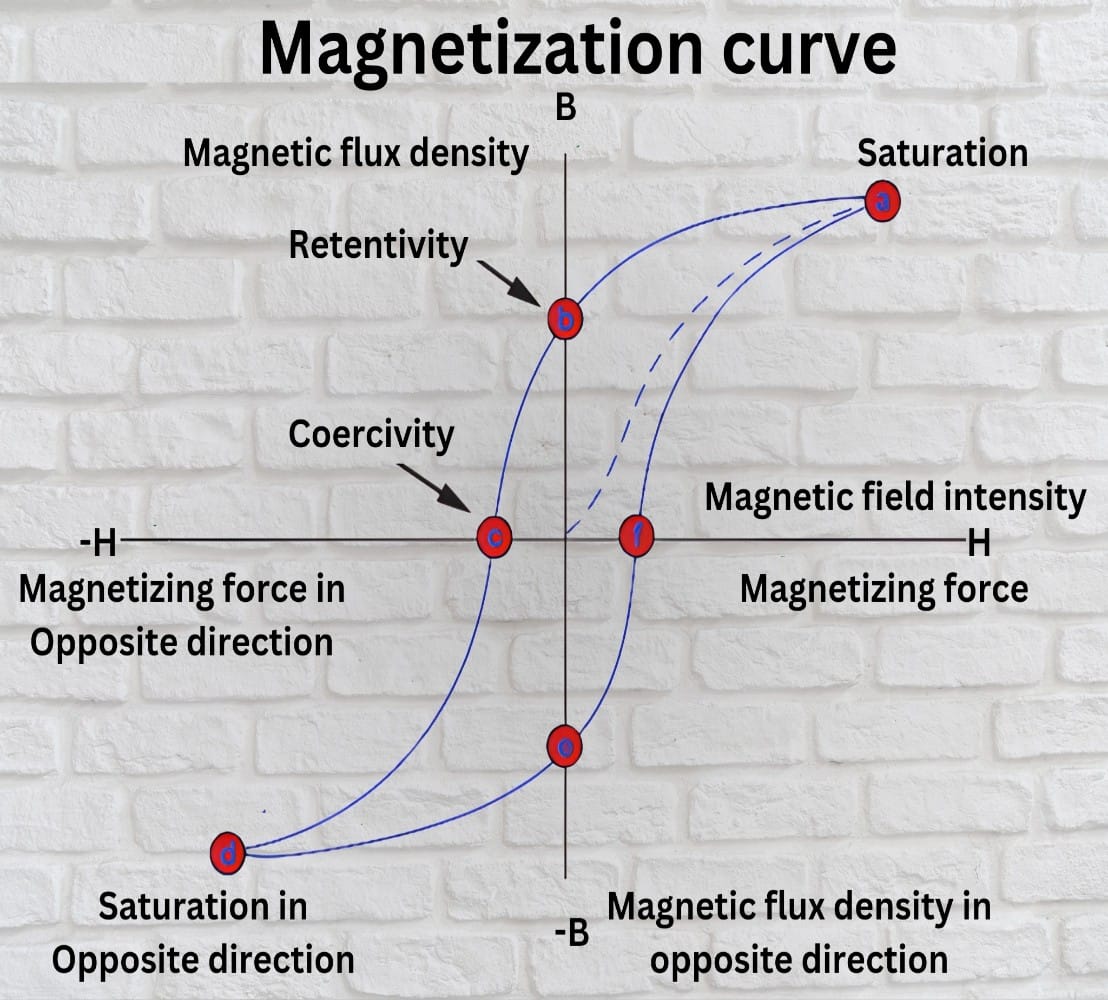
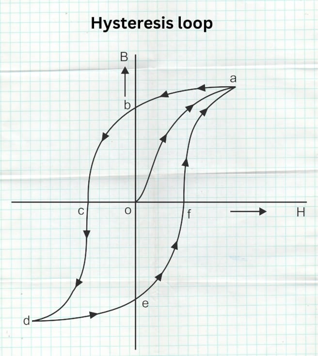
- As the field intensity HH gradually increases—by raising the current in the solenoid through a reduction in resistance RR—the flux density BB also rises until it reaches the saturation point at ‘a’. This produces the curve segment oa. If you then reduce the magnetizing force by lowering the current to zero, the flux density does not drop to zero. Instead, it follows the curve ab, as shown in Fig. 6. Even when the magnetizing force HH becomes zero, the flux density retains a value of ob.
Figure 6
- The flux density ob retained by a magnetic material is called residual magnetism, and its ability to retain it is known as retentivity. To demagnetize the ring, reverse the magnetizing force H by switching the double-pole double-throw switch to position ‘2’. As H increases in the reverse direction, flux density decreases to zero along curve bc. Thus, applying magnetizing force oc removes the residual magnetism.
-
The magnetizing force oc needed to remove residual magnetism is called the coercive force. To complete the hysteresis loop, continue increasing H in the reverse direction until saturation at point ‘d’, following path cd. As H returns to zero, the curve follows de, where oe is the new residual magnetism in the reverse direction.
-
Next, increase H in the positive direction by switching back to position ‘1’ and raising the solenoid current. The curve follows path efa, completing the loop. Here, of is the coercive force needed to erase the residual magnetism oe.
-
Therefore, cfc_f represents the total coercive force needed in a full magnetization cycle in order to remove residual magnetism. Since hysteresis means "lagging behind," with the magnetic flux density BB lagging behind the magnetizing force HH, the resulting loop abcdefaabcdefa is called the hysteresis loop. As such, this loop visually demonstrates energy loss in the form of heat during each cycle of magnetization. Consequently, understanding this behavior is essential in designing efficient magnetic materials and devices.
