Introduction
Machining processes are essential in contemporary manufacturing, transforming raw materials into precise components for different industries. Orthogonal cutting and oblique cutting are key techniques that are important for achieving efficiency, surface finish, and tool lifespan in machining operations.In this blog we will study in details about Orthogonal and Oblique Cutting.
Before we delve into Orthogonal and Oblique Cutting we let's take a closer look at metal cutting process.
Principle of metal cutting
- Relative motion between the cutting tool and work piece.
- Tool edge comes in contact with the metal, it exerts pressure on metal.
- Metal severely compressed,causes high temperate shear stress in metal.
- As tool advance, stress in the work piece just ahead of cutting tool reaches a value exceeding the ultimate strength of metal.
- Particles of metal start shearing away and flow plastically along the shear plane.
- It forms segment of chip which moves up alone the face of the tool.
- Cycle of compression, plastic flow and shearing away is repeated.
- It results into from of a continuously flowing chip.
Mechanism of Metal Cutting
During the flow of the chip on the rake surface of the cutting tool, the temperature of the newly formed chip increases primarily due to friction. As a result, a portion of this chip may get welded automatically to the rake surface. However, the continuous formation of new chip material exerts compressive force on this welded layer. Consequently, this force causes the welded chip to undergo further deformation, leading to what is known as secondary shear. This shear, occurring beneath the chip-tool interface, is therefore referred to as the secondary shear zone.
In addition, in the context of metal cutting, the line generated by the cutting motion is known as the generatrix, while the line formed by the feed motion is referred to as the directrix. Together, these lines define the geometry and surface pattern of the machined component.
Definition of Orthogonal and Oblique Cutting
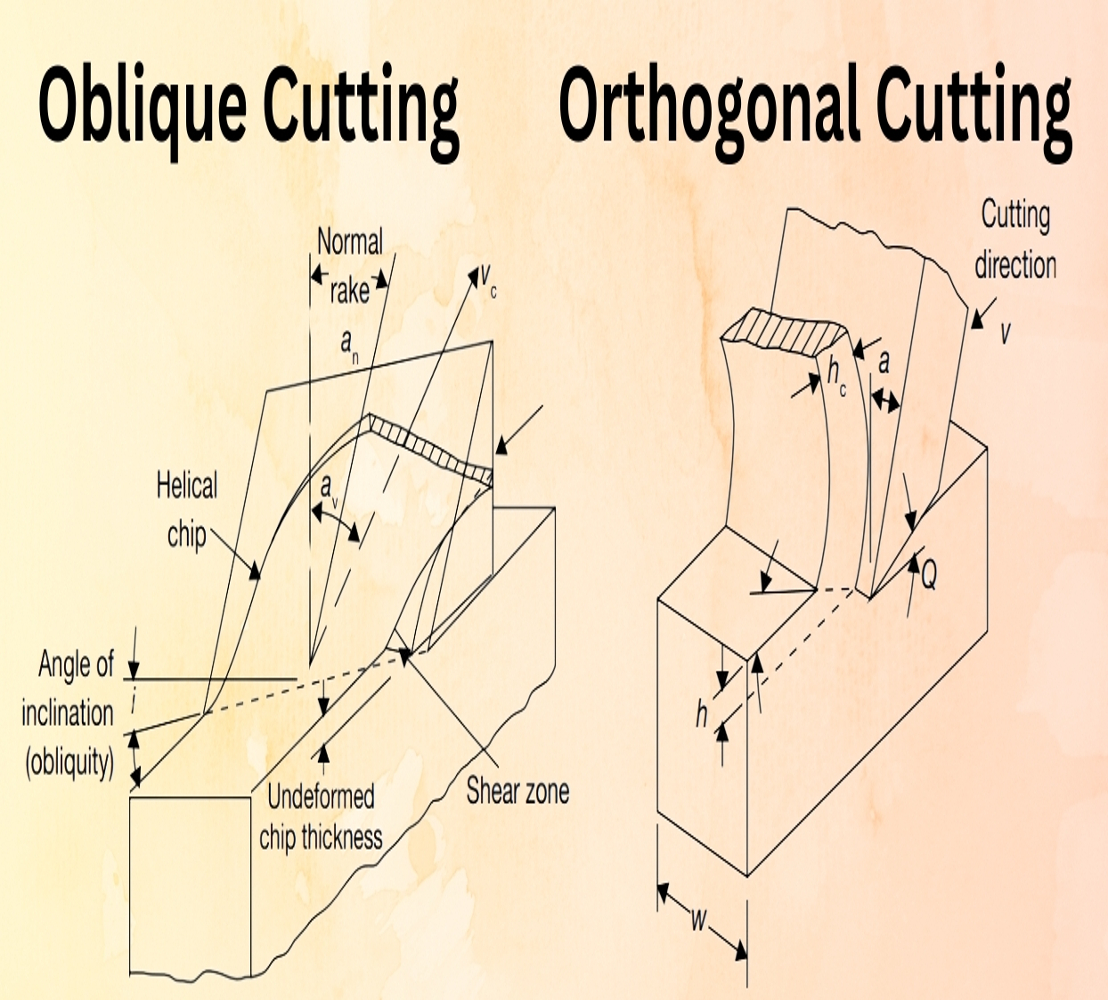
- Orthogonal cutting, also referred to as 90-degree cutting, is when the tool is perpendicular to the workpiece. The cutting edge aligns with the feed motion, resulting in a right angle. It is commonly employed in operations such as turning and facing.
- In contrast, oblique cutting uses a tool that is tilted at an angle other than 90 degrees to the workpiece surface. Unlike orthogonal cutting, where the cutting edge is perpendicular, oblique cutting involves a more complex geometry. As a result, it is more intricate and requires careful control of cutting parameters. Typically, this method is observed in operations such as milling, shaping, and certain specific turning tasks. Moreover, due to the angled approach, the chip flows sideways, which affects heat distribution and tool wear. Therefore, understanding the mechanics of oblique cutting is essential for precision and efficiency in these machining processes.
Differences Between Orthogonal and Oblique Cutting
| Orthogonal Cutting | Oblique Cutting |
|---|---|
| The cutting edge of the tool is perpendicular to the direction of the tool travel. |
The cutting edge of the tool is inclined at some acute angle to the direction of the tool travel. |
| The cutting edge clears the width of the workpiece on either end. | The cutting edge may or may not clear the width of the workpiece on either end. |
| The chip flows over the rake surface of the cutting tool in the direction perpendicular to the cutting edge. The shape of the chip coil is tight flat spiral. |
The chip flows on the rake surface of the tool making an angle with the normal on the cutting edge.The chip flows sideways in a long curl. |
| Only two components of the cutting force act on the cutting edge. | Three components of the forces mutually perpendicular act at the cutting edge. |
| Maximum chip thickness occurs at the middle. | The maximum chip thickness may not occur at the middle. |
| For same feed and depth of cut, the force which shears the metal acts on a smaller area and therefore, the heat developed per unit area due to friction along the tool work interface is more and tool life is less. |
Force of cutting acts on longer area and therefore, the heat developed per unit area due to friction along the tool work interface is more and tool life is less. |
Conclusion
Orthogonal and oblique cutting each offer unique advantages and challenges in machining. The choice depends on factors like tool life, cutting forces, and surface finish. Understanding their differences helps engineers optimize efficiency and precision in manufacturing.


