Introduction
The activation of a thyristor is an essential part of how it functions, deciding when the device transitions from not conducting to conducting. It is crucial to comprehend the different types and methods of thyristor triggering in order to design and manage power electronic circuits efficiently. In this detailed blog post, we will examine the complexities of thyristor triggering, discussing its various types, operational principles, and widespread uses in different sectors.
Understanding Thyristor Triggering
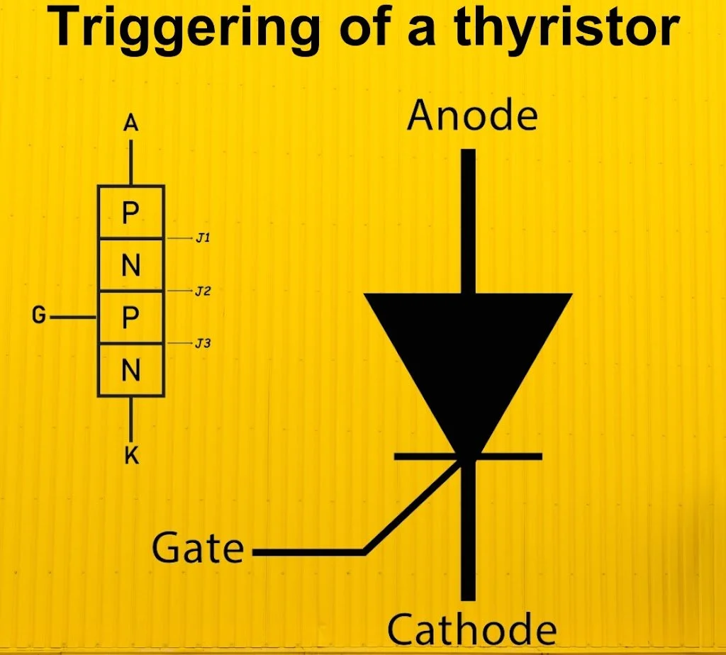
A thyristor, a semiconductor component, boasts three access points: the anode, cathode, and the gate. Its functionality hinges on two primary conditions. First, the "forward block" state prevents any current flow. Second, the "forward conduct" state enables electrical conduction.To switch the thyristor into the conducting mode, one must furnish a distinct signal, often a voltage, to the gate connection.
Types of Thyristor Triggering
1.Forward Voltage Triggering
If the gate circuit is not connected, the thyristor's forward voltage, from anode to cathode, is increased. This rise triggers an avalanche breakdown inside the reverse-biased junction `J_2`. This breakdown transpires at a particular voltage level, defined as the forward breakover voltage and symbolized as `V_{BO}`. Upon reaching `V_{BO}`, the thyristor's operational mode abruptly switches. The device shifts from its OFF condition – represented by a high voltage and negligible leakage current – to its ON condition. This ON state is distinguished by a small voltage drop and a considerable forward current.When the thyristor is ON, the forward voltage drop across the SCR settles between approximately 1 to 1.5 V. Furthermore, this voltage demonstrates a slight augmentation in correlation to changes in the load current.
2.Thermal Triggering (Temperature Triggering)
Similar to other semiconductor components, the depletion region within a thyristor decreases in width as the temperature of its junction increases. Consequently, in the context of a thyristor, bringing the anode-cathode voltage close to the breakdown threshold can result in device activation by increasing the junction temperature. Specifically, when the temperature reaches a particular critical level, bounded by its operational limits, the reverse-biased junction undergoes a breakdown, initiating device conduction. This technique, where thermal energy is used to enable the device, is termed thermal triggering.
3.Radiation Triggering (Light Triggering)
This leads to instantaneous flow of current within the device and the triggering of the device. For radiation triggering to occur, the device must have high value of rate of change of voltage `({dv}/dt)`. Light activated silicon controlled rectifier (LASCR) and light activated silicon controlled switch (LASCS) are the examples of this type of triggering.
4.`left(frac{dv}{dt}right)` Triggering
5.Gate Triggering
The predominant method utilized to initiate SCR functionality involves applying a positive signal. This approach enjoys widespread use in research environments, consistently acting as the main activator for almost every SCR available. Introducing such a signal to the gate terminal allows the SCR to turn on effectively, preempting the attainment of its breakover voltage level. With meticulous control, maintaining observance of the component's performance parameters, inclusive of upper and lower gate current limits, it becomes possible to accurately manage the period during which the SCR conducts current.
Gate triggering specifically involves injecting a signal that passes between the gate and the cathode connectors of the SCR. The signals used can vary, with three common options being direct current (DC) signals, pulse signals, and alternating current (AC) signals.
1.D.C. Gate Triggering
- This kind of triggering approach involves applying a direct current (DC) voltage. Crucially, this voltage must have both the correct size and polarity. The voltage is set between the gate and the cathode of the component. This causes the gate to become positive relative to the cathode.As the voltage rises, it will eventually reach a threshold. At this point, there is enough gate current to activate the component. Once that happens, the device begins to conduct electricity.
- A major weakness inherent in this design lies in the shared d.c. nature of the power and control pathways, resulting in a lack of electrical isolation between them.Furthermore, this method presents the issue of needing a constant d.c. signal applied to the gate, ultimately leading to heightened power dissipation within the gate itself.
2.A.C. Gate Triggering
- The gate signal for thyristor control in AC systems predominantly originates from an AC source. The design's popularity stems from its guarantee of a solid separation between power delivery systems and the regulating components. Furthermore, fine-tuning the firing angle, which is crucial for operation, is straightforward. It only involves modifying the phase angle of the signal that governs the process.
- When it's switched on, the gate's control signal stays powered for a period equivalent to one half of a complete cycle. During the segment of the cycle where the direction is wrong, voltage, which is of opposite polarity, travels from the gate toward the cathode. This setup causes a major difficulty: it requires a transformer just for this function. This also results in a lowering of the AC voltage, which, inevitably, leads to a rise in the entire financial burden.
3.Pulse Gate Triggering
- This is the most popular method for triggering the device. In this method, the gate drive consists of a single pulse appearing periodically or a sequence of high frequency pulses. This is known as carrier frequency gating. A pulse transformer is used for isolation.
- The main advantage of this method is that there is no need of applying continuous signals and hence,the gate losses are very much reduced. Electrical isolation is also provided between the main device supply and its gating signals.
Triggering Characteristics of thyristor
1.Delay time (`t_d`)
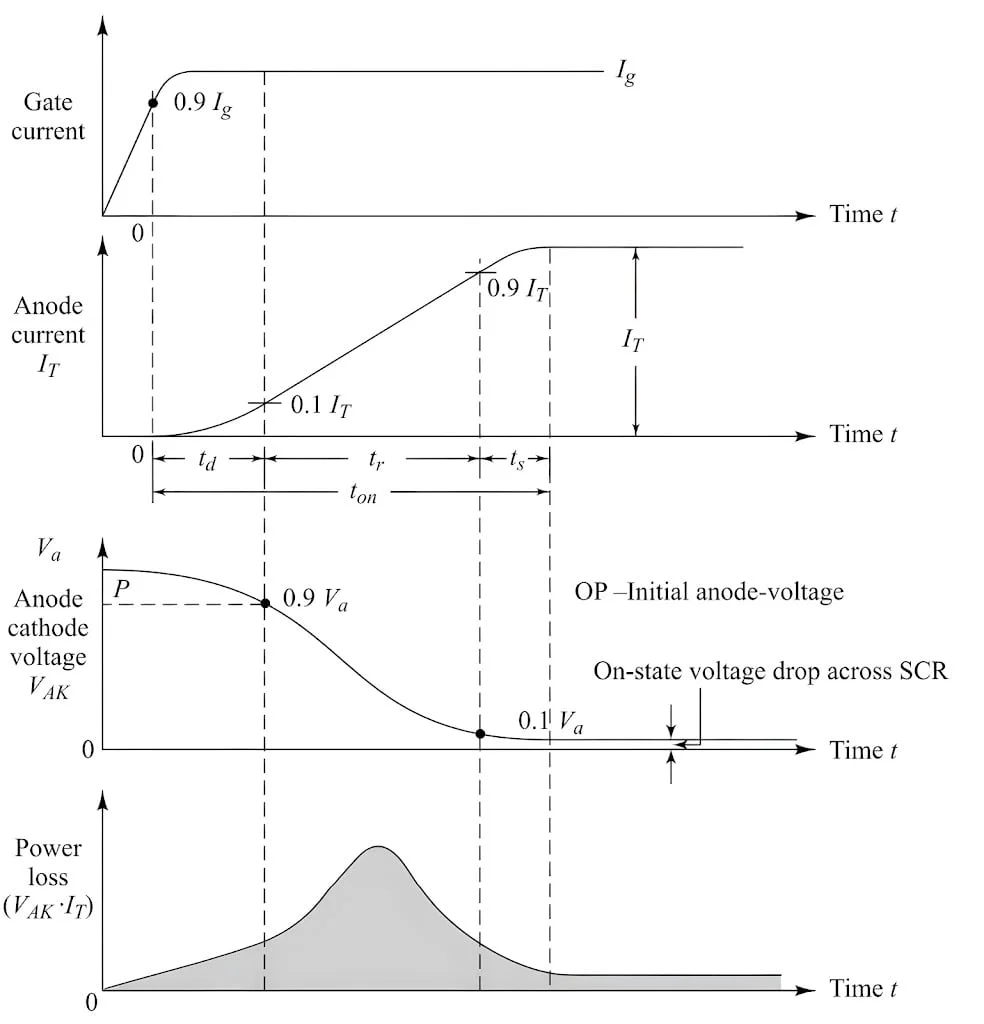
- The turn-on delay denotes a particular timeframe within a thyristor's operating sequence. The timing begins when the gate current achieves 90% of its constant, ultimate magnitude. The timer ceases when the anode current, the principal current within the thyristor, attains one-tenth of its ultimate value.Another way to define this initialization delay centers on how the anode voltage changes. From this view, the turn-on delay is the period where the anode voltage descends from its initial level, designated `V_a`, to a level that is 90% of the original `V_a`.
- The gate current has non-uniform distribution of current density over the cathode surface due to the p-layer. Its value is much higher near the gate but decreases rapidly as the distance from the gate increases. It shows that during `t_d`,anode current flows in a narrow region near the gate where gate current density is the highest.
2.Rise Time (`t_r`)
- A vital characteristic, turn-on time, specifies the pace at which the anode current increases. Essentially, it measures the time necessary for the current to rise, transitioning from a tenth to nine-tenths of its stable, ultimate value. Considering a separate aspect, the turn-on time also relates to voltage changes. The decline in forward blocking voltage, which typically initiates at a high level, equally characterizes this property through the timeframe involved.More precisely, the voltage diminishes, beginning at the off-state voltage, known as OP, specifically from 90% down to 10% of its starting level.
- This time is inversely proportional to the magnitude of gate current and its build up rate. Thus, `t_r` can be minimized if high and steep current pulses are applied to the gate.
- For series RL circuit, the rate of rise of anode current is slow,therefore, tr is more and for the RC series circuit, `({di}/dt)` is high thus `t_r` is less.
3.Spread-time (`t_s`)
- The turn-on duration represents the interval during which the forward-blocking voltage diminishes from a tenth of its value to the voltage present when the device is in an "on" state, typically spanning from 1 to 1.5 volts.After the spread time, anode current attains steady-state values and the voltage drop across SCR is equal to the on-state voltage drop of the order of 1 to 1.5 V.
4.Turn-on Time (`T_{on}`)
- This is the sum of the delay time, rise-time and spread time. This is typically of the order of 1 to 4 µs, depends upon the anode circuit parameters and the gate signal waveshapes.The width of the firing pulse should, therefore, be more than 10 µs, preferably in the range of 20 to 100 µs. The amplitude of the gate-pulse should be 3 to 5 times the minimum gate current required to trigger the SCR.
- From Fig. 1, it is noted that during rise-time, the SCR carries a large forward current and supports an appreciable forward voltage. This may result in high instantaneous power dissipation creating local internal hot spots which could destroy the device. It is, therefore, necessary to limit the rate of rise of current. In most cases, a small inductor, commonly known as a di/dt choke, finds its place within the anode circuit. Its fundamental role is to limit how quickly the anode current rises or falls.
Applications of Thyristor Triggering
- Power Control Systems: The function of thyristors in power control systems includes voltage regulation, phase regulation, and power switching, in industrial equipment, motor drives, and heating systems.
- Inverters and Converters: Thyristors enable AC to DC conversion, DC to AC inversion, and frequency control inverter and converters for renewable energy sources, UPS systems, and motor drives.
- Electric Vehicles (EVs): In the realm of electric vehicle (EV) powertrains, the thyristor serves as a crucial component, facilitating essential functions. Its application encompasses precise motor control, efficient battery charging and discharging processes, and the implementation of regenerative braking. Through its integration, the overall efficiency and dependability of the EV's powertrain are significantly enhanced.
- HVDC Transmission: HVDC transmission systems employ thyristor-controlled converters based on the triggering of pulse width modulation for the purpose of long-distance power transfer, grid interconnection as well as renewables integration.
- Welding Equipment: Thyristors play a crucial role in welding equipment, serving to precisely regulate current flow. They also contribute to the stabilization of the arc and facilitate modifications to the welding procedure itself.
- Light Dimmers and Controllers: Thyristor-based light dimmers and controllers which adaptable level of brightness, ambiance and energy saving provide solutions in the lighting systems for residential, commercial, and industrial use.
- Power Factor Correction: Thyristors made it possible to integrate power factor correction (PFC) circuits to reactive power compensation, thereby improving energy efficiency and grid stability.
- HVAC Systems: HVAC setups, encompassing heating, ventilation, and air conditioning, often employ thyristor triggering techniques. These are particularly useful for managing temperatures, adjusting the velocity of fans, and facilitating the conservation of energy throughout the system's processes.
Conclusion
In summary, it is crucial to comprehend the varieties and processes of thyristor activation in order to create effective and dependable power electronic systems for a range of uses. Advancements in thyristor triggering technologies will continue to improve due to ongoing research and development efforts, resulting in enhanced performance.